American Tech Supply is now an authorized Hyperline distributor
From copper to fiber, the Hyperline system of products includes everything you need for installation, termination, testing and troubleshooting. And our level of technical expertise, training and customer support ensures that your total cost of ownership is kept to a minimum.
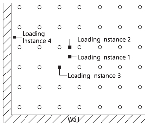
Loading capacity
Loading instances
Permissible loading capacity determined by means of testing and calculations carried out in conjunction with official authorities. The results produced from this are substantiated by certificates of conformity for the standards DIN EN 12 825 and DIN EN 13 213.
The following items are decisive and differ in:
Size of load
Supporting surface of the load forcer
Arrangement of the load on the test indentor
Safety factor
Both for access floors and for hollow floors, the point load is the critical loading applied. The flooring systems are assigned to a loading capacity and displacement rating on the basis of a static loading to be expected. Linear loads and distributed loads are not generally taken into account, because the loading capacity of the hollow and access flooring constructions is usually greater than the loading capacity of the structural floor.
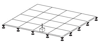
Point loading
To determine the point load, a static load (such as a table leg) is simulated. On the basis of the permissible load determined in this way, classification is usually made for the appropriate loading and displacement rating. In accordance with standard practice, the load is applied with a 1” x 1” (25 x 25 mm) indentor.
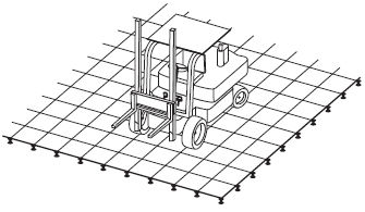
Dynamic loading
To determine the permissible dynamic load (such as a forklift), the following has to be taken into account: The following items are decisive and differ in:
The unloaded weight of the vehicle
The total weight of the vehicle
Max wheel load
The contact surface of the tires or rollers
Distance between the axles
Max traveling and pulling speeds
Quantity, diameter, width and material of wheels or rollers
Max acceleration and deceleration of the lifting motion
Safety factor
On the basis of the facts given above, an appropriate load factor is determined for the static load (permissible overall weight of a vehicle) and multiplied by the max permissible static load. When selecting a floor covering, one must be sure that the floor covering and adhesive meet these special requirements.
Statics in accordance with DIN EN 12 825
To determine the maximum load and appropriate groupings, EN 12825 for access floors provides for a system test consisting of a panel and pedestal (substructure). The loading is applied to the system by an indentor, measuring 1” x 1” (25 x 25 mm). The criterion for failure for classification of the system is the breaking load and the deflection.
Load class
Class1
Collapse load?2(N)
Design load?3(N)
Load class4
Examples of use and applications
1
>= 4000
2000
2
Offices with few visitors; without corridors
2
>= 6000
3000
3
Standard office areas
3
>= 8000
4000
4
Industrial floors with light traffic, storage rooms, workshops with light use, libraries
4
>= 10000
5000
5
Industrial floors with light traffic, storage rooms, workshops with light use, libraries
5
>= 12000
>= 6000
4
Floors with factory truck traffic, industrial and workshop floors, vault rooms
1) Loading certification according to DIN EN 12825 / DIN EN 13213
2) To determine the breaking load, the load is applied by means of a 1” x 1” (25 x 25 mm) thrust plate at the weakest point in the panel and increased until the system fails
3) The design load results from the collapse load divided by the load factor ? = 2
4) Loading classification according to the application guideline for access floors
5) Higher collapse/design loads are necessary for access floors with high requirements specified in individual cases. These should be stipulated in steps of 2000 / 1000 N each
Displacement rating
With loading amounting to the imposed load (this being the collapse load divided by the safety factor), the vertical displacement measured must not fall short of the values given in the chart.
Load class
Class
Maximum displacement, in (mm)
A
0.1 (2.5)
B
0.12 (3.0)
C
0.16 (4.0)
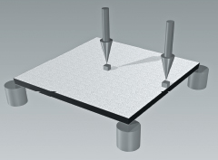
Statics in accordance with RAL-GZ 941
RAL-GZ 941 describes a test of components for classification in the load class. The access floor panel and pedestal are tested and classified separately. The maximum effect of loading is applied to the access floor panel with an indentor measuring 1” x 1” (25 x 25 mm). The access floor panel is supported on solid cylinders. The criterion for failure is the breaking load and the maximum panel deflection of 0.08” (2 mm) (l/300).
Load class
Class1
Collapse load?2?(N)
Static design point load?3?(N)
Deflection4?in, (mm)
Examples of use and applications
1
>= 6000
3000
max 0.08 (2)
Offices with high density of communication equipment, telephone exchanges, design offices, auditoria, training & treatment rooms
2
>= 8000
4000
max 0.08 (2)
Commercial computer rooms and secondary buildings
3
>= 10000
5000
max 0.08 (2)
Computer rooms with heightened requirements, printing rooms, industrial floors with light traffic, storage rooms, workshops with light use and libraries
4
>= 10000
5000
max 0.08 (2)
Floors with forklift traffic, industrial and workshop floors and vault rooms
5
>= 12000
>= 6000
65?and higher
Floors with factory truck traffic, industrial and workshop floors, vault rooms
1) Loading certification according to RAL-GZ 941
2) To determine the breaking load, the load is applied by means of a 1” x 1” (25 x 25 mm) thrust plate at the weakest point in the panel and increased until the panel fails
3) The static design load results from the breaking load divided by the safety factor ? = min. 2
4) When the static design load is loaded, the maximum deflection may be l / 300
Call (866) 342-3721 Or Click On The Chat Button At The Top Of The Page To Talk To One Of Our Representatives