From copper to fiber, the Hyperline system of products includes everything you need for installation, termination, testing and troubleshooting. And our level of technical expertise, training and customer support ensures that your total cost of ownership is kept to a minimum.
cable, vdsl, patch
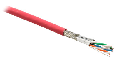
Shielded Twisted Pair Cable (SSTP), 4 pairs, Solid, Indoor, 23 AWG, LSZH, Category 7 (1000 MHz)

 |
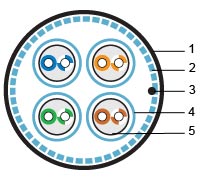
1 – Jacket 2 – Shield-braid 3 – Drain wire 4 – Shield-foil 5 – Solid twisted pair |
| Meets IEC 61156-5, IEC 61156-5 category 5e, 6, 7 requirements and ISO/IEC 11801 category 7 requirements Fire protection – CM The cable meets UL 1581 VW-1, IEC 60332-1 fire safety standard |
| Shielded Copper cable, 4 pairs, category 7 (1000 MHz, 10GbE), solid 4 separately foil-shielded pairs General shield: wire braid Cable is used for indoor installation |
| Conductive material: wire made of soft annealed electrolytic copper Conductor insulation: cellular PO The cable jacket: FR-LSZH Shield: every pair is separately shielded with polyester aluminum foil (foil is on the outside), which covers 100% of twisted pair General shield: tin Copper braid - 60% minimum Drain wire: tinned copper |
| Conductor diameter: 23 AWG Insulated conductor diameter: 1.34 mm (0.05") Outer cable diameter: 8,0 mm (0.31") Drain wire diameter: 24 AWG Maximum bend radius: 120 mm (4.72") Pulling strength: 140 N max. Operating temperature: -40°C - +70°C (-40°F - +158°F) Weight per 1000 ft (304.8 m): 43,65 lbs (19.8 kg) Standard package: 500 m (1640 ft) |
| Frequency, MHz | Attenuation at 20°C, dB/100m | PS NEXT, dB | NEXT, dB | RL, dB | PS ANEXT, dB | PS ELFEXT, dB | ELFEXT, dB | |||||||
|---|---|---|---|---|---|---|---|---|---|---|---|---|---|---|
| Typical Value | Cat. 7 | Typical Value | Cat. 7 | Typical Value | Cat. 7 | Typical Value | Cat. 7 | Typical Value | Cat. 7 | Typical Value | Cat. 7 | Typical Value | Cat. 7 | |
| 1 | 2.0 | 2.0 | 105.0 | 99.4 | 108.0 | 102.4 | 22.0 | 20.0 | 68.0 | - | 95.0 | 75.0 | 98.0 | 78.0 |
| 4 | 3.6 | 3.7 | 98.0 | 90.4 | 101.0 | 93.4 | 25.0 | 23.0 | 68.0 | - | 90.0 | 75.0 | 93.0 | 78.0 |
| 10 | 5.6 | 5.8 | 95.0 | 84.4 | 98.0 | 87.4 | 28.0 | 25.0 | 68.0 | - | 86.0 | 71.0 | 89.0 | 74.0 |
| 20 | 7.9 | 8.3 | 90.0 | 80.0 | 93.0 | 83.0 | 28.0 | 25.0 | 68.0 | - | 80.0 | 65.0 | 83.0 | 68.0 |
| 30 | 9.7 | 10.2 | 85.0 | 77.2 | 88.0 | 80.2 | 27.0 | 23.8 | 68.0 | - | 76.0 | 61.5 | 79.0 | 64.5 |
| 100 | 18.0 | 19.0 | 80.0 | 69.4 | 83.0 | 72.4 | 24.0 | 21.1 | 68.0 | - | 66.0 | 51.0 | 69.0 | 54.0 |
| 150 | 22.4 | 23.6 | 78.0 | 66.7 | 81.0 | 69.7 | 22.0 | 18.8 | 65.0 | - | 63.0 | 47.5 | 66.0 | 50.5 |
| 200 | 26.0 | 27.5 | 78.0 | 65.0 | 81.0 | 68.0 | 21.0 | 18.0 | 65.0 | - | 60.0 | 45.0 | 63.0 | 48.0 |
| 250 | 29.4 | 31.0 | 75.0 | 63.4 | 78.0 | 66.4 | 20.0 | 17.3 | 62.0 | - | 58.0 | 43.0 | 61.0 | 46.0 |
| 300 | 32.5 | 34.2 | 75.0 | 62.2 | 78.0 | 65.2 | 19.0 | 17.3 | 62.0 | - | 52.0 | 41.5 | 55.0 | 44.5 |
| 400 | 38.0 | 40.0 | 70.0 | 60.4 | 73.0 | 63.4 | 19.0 | 17.3 | 62.0 | - | 49.0 | 38.9 | 52.0 | 41.9 |
| 500 | 43.0 | 45.2 | 70.0 | 58.9 | 73.0 | 61.9 | 19.0 | 17.3 | 62.0 | - | 47.0 | 37.0 | 50.0 | 40.0 |
| 600 | 47.6 | 50.1 | 70.0 | 57.7 | 73.0 | 60.7 | 19.0 | 17.3 | 62.0 | - | 45.0 | 35.4 | 48.0 | 38.4 |
| Conductor resistance at 20°C (68°F) | 80.0 Ohm/km (128.75 Ohm/mile) |
| DC Resistance Unbalance | 2% max |
| Resistance at frequency 1-600 MHz | 100 ± 15 Ohm |
| Transfer impedance at frequency 1-10 MHz | 5 MOhm/m (1.52 MOhm/ft) max |
| Capacitive unbalance at frequency 1 kHz | 1.2 pF/m (0.36 pF/ft) max |
| Maximum voltage | 60 V RMS |
| Dielectric rigidity | 700 V/min |
| Insulation resistance at 20°C (68°F) | 152 MOhm/km (244.62 MOhm/mile) minimum |
| Propagation velocity | 79-80% |
| Max propagation delay at frequency 1 MHz | 5.3 ns/m (1.61 ns/ft) |
| Max propagation delay at frequency 10 MHz | 5.0 ns/m (1.52 ns/ft) |
| Max propagation delay at frequency 100-600 MHz | 5.0 ns/m (1.52 ns/ft) |
| Max derivation of propagation delay at frequency 1-600 MHz | 15 ns/100 m (4.57 ns/100 ft) |
| SSTP4-C7-SOLID-INDOOR | Shielded twisted pair cable (SSTP), 4 pairs, solid, indoor, 23 AWG, LSZH, category 7 (1000 MHz) |

Call (866) 342-3721 Or Click On The Chat Button At The Top Of The Page To Talk To One Of Our Representatives

Patch Panels
Work Area Outlets
Keystone Jacks
Modular Plugs
Cross Connection
Fiber Optic
Cable Managers
Patch Cords
Cables
Installation Accessories
Tools
Racks and Cabinets
Power Distribution Units
Access Floors
Defem Wire Mesh Cable Trays and CombiRack System
Axelent Cable Trays

|
|


