 |
American Owned and Operated |
Raceway Systems-Cable Management Solutions- Ladder Racks- Wholesale ladder Racks-Cable Management Solutions- WireTrays - Distribution Racks- Raceway- Relay Racks- CableTies-Cable Management- Cable Wraps-Finger Duct Panels
American Tech Supply carries a complete line of cable management solutions including cable trays, wire trays, ladder racks, distribution racks, raceway and raceway systems that can be tailored to meet your specific needs. ATS provides a complete line of cable management products from several manufacturers including Cablofil, Snaketray, Hendry, Newton, Signamax, Ortronics, ICC Ladder Racks, Cable Manager,Homaco, ADC, Bailywick Systems, Damac, ADC, and others. We offer wholesale ladder rack options to make every telephone closet or network bay installation neat, well organized and secure.American Tech Supply's ladder racks are are available in 3, 4, 5 6, 7 ft, 10 ft. versions, and come in either a black powder coated or polished aluminum finish. For added cable management, vertical cable channels can be added to standard distribution racks. Our new ladder racks come in 5 foot lengths that contracotrs have been requesting to lower shipping costs. Now we can ship several ladder racks- 5 feet or less via UPS-meaning lower shipping costs. For Raceway Systems-more info
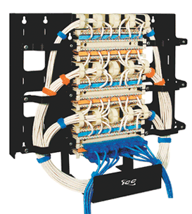 CABLE Management

 Cable Management Racks- Distribution Racks Below
Cable Management Racks- Accessories
Raceway Systems
Vertical Rings
Rack Mount Rear Cable Management Bar
Metal Ring Panels
Metal Interbay Panels
Extended Cable Management Bracket
Clip Panels
Cable Management Ring Panels
Cable Management Panel Covers
Cable Management Interbay Panels
Cable Management Finger Duct Panels
Blank Panels
Cable Management Racks combine the features of a high quality relay rack, as well as effective cable routing and raceway facilities, all in one complete unit. All aluminum cable management rack allows for the mounting of a wide variety of 19 inch wide patch panels, hubs, switches, and related rack mount equipment. The rack is supplied with cable hangers, cable ties and generous provisions for organizing incoming cables for termination with effective patch cord management on the front. Racks are shipped with all assembly required plus an accessory pack that includes 20 cable ties, 16 cable hangers, 40 cuphead mounting screws, and grommeting for cable routing cutouts.
Standard equipments racks are designed for 19 inch rack mount equipment. Racks are constructed of aluminum and are available in a variety of standard heights. Each rack is drilled and tapped on both the front and the rear rails with 10-32 holes on EIA spacing. Standard rack finish is black. Racks are packaged knocked down for easy shipment.
Part Number |
Cable Management Rack Description |
1977-1032B |
Signamax Cable Management Rack, 19"W x 84"H, Black Finish, 10-32 Holes |
Cable Management Racks
Part Number |
Cable Management Rack Description |
RR-84B |
Signamax Equipment Rack, 19"W x 84"H, Black Finish, 10-32 Holes |
RR-48B |
Signamax Equipment Rack, 19"W x 48"H, Black Finish, 10-32 Holes |
RR-84 |
Signamax Equipment Rack, 19"W x 84"H, Milled Finish, 10-32 Holes |
RR-48 |
Signamax Equipment Rack, 19"W x 48"H, Milled Finish, 10-32 Holes |
------------------------------
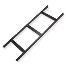 Five Foot Ladder Racks-ICC Part Number: ICCMSLST05
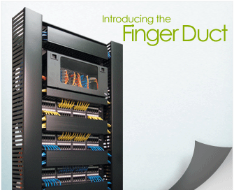 ICC Finger Duct- Click Here -------
 ------- ICC Racks- Cable Management
 Horizontal Finger Duct
  Vertical Finger Duct
 |
Distribution Racks-Click Here --------Ladder Racks -Click Here
NEW.......Cable Wrap-CableTies.....


![]() Cable
Ties-Cable Wrap-Cable Catch-Cable Hangers
Cable
Ties-Cable Wrap-Cable Catch-Cable Hangers
ATS's cable management racks are made of rugged steel and feature a black powder coating. All rack side rails have openings for cable routing, and provide cable tie anchors in various locations. These racks are available in 4 and 7 foot models. In addition to floor mounted racks, a variety of wall mount racks and brackets are available to fill specialized applications. To add to the versatility of the distribution and cable management racks, ATS offers a selection of shelves to support components that do not need to be rack mounted.
Cable management panels are available to support bulk cable or patch cords horizontally or vertically. These panels come with standard metal, or durable plastic rings. Plastic snap-on covers can be added to the plastic panels to create a neat, well-organized appearance. Brackets, vertical rings, and management bars round out ATS's Cable Management Solution.
New Ladder Rack Systems !
Call For Pricing Today at (866) 650-DATA
Wholesale Ladder Racks, Ladder Rack Systems & Raceway Systems
|
NEW Ladder Rack Runway Mounting Kits NEW Straight Ladder Rack Runway
Key features:
ICC Raceway System Cutting Tool-Part# ICACSTPE60 This ICC Raceway System Cutting tool make cutting raceway a "snap".
| |
|
|
Designed to complement American Tech Supply's line of racks, panels and cross-connect products, we offer Hendry, B-line, NewtonKewaunee and ICC's, ladder rack system. This ladder rack system offers a complete set of cable installation, routing and management components that are engineered for configuration flexibility and installation versatility. Please note our ladder rack products below including our ladder rack inside corner, ladder rack outside corner, and ladder rack flat turn models below.

ICC Raceway System Cutting Tool-Part# ICACSTPE60 This ICC Raceway System Cutting tool make cutting raceway a "snap".
|
Runway section is designed to support horizontal cable running over-head. Constructed of heavy duty 16-gauge steel with a durable powder coated finish, it can be easily attached to all ICC racks. Part Number: ICCMSLST10 10 ft*., Runway, 12 in. Wide *We Have Shorter Lengths!! | Runway radius bend section is used to change the horizontal cable running over-head in a 90° vertical direction to route cables downward to a vertical ladder. Part Number: ICCMSLOR90 Runway Radius Bend, 12 in. Wide | Runway
radius bend section is used to change the horizontal cable running over-head in
a 90° vertical direction to support ceiling cable entry. Part Number:ICCMSLIR90 Runway Radius Bend, 12 in. Wide | Turn section is designed to change the horizontal cable running over-head in a 90° flat turn. Part Number:ICCMSLFT90 Runway 90° Turn, 12 in. Wide |
 |
 |
 |
 |
Click Here for Installation Instructions and detailed pictures of Ladder Rack
| ITEM NUMBER | DESCRIPTION | ||
| ICCMSLST10 | Runway Section, 12-inches Wide x 10-foot Length | ||
| ICCMSLFT90 | 90? Turn Section, 12-inches Wide, flat turn. | ||
| ICCMSLIR90 | Inside Radius Bend Section, 12-inches Wide | ||
| ICCMSLOR90 | Outside Radius Bend Section, 12-inches Wide | ||
| ICCMSLAWSK | Kit, Wall Support, 12-inches Wide | ||
| ICCMSLTWSK | Kit, Wall Support, Triangle, 12-inches Wide | ||
| ICCMSLVWBK | Bracket, Vertical Wall Mount | ||
| ICCMSLCMRK | Kit, Ceiling Mount and Rod (2 Threaded rods included) | ||
| ICCMSLMFFK | Kit, Foot Floor Mount | ||
| ICCMSLRRBK | Bracket, Ladder to Relay Rack, 12-inches Wide | ||
| ICCMSLEBSK | Kit, End-to-end Butt Splice | ||
| ICCMSLTJSK | Kit, Runway Section, T-Junction Splice | ||
| ICCMSLCRPK | Kit, Cable Retaining Posts (includes 2 posts) | ||
| ICCMSLCRDK | Runway Center Radius Drop, 12-inches Wide | ||
| Miracel 19" Distribution Rack-Lab Rack NO 19 | ||||||||||||||||||||||||||||||||||||||||||||||||||||||||||||||||||||||||||||||||||||||||||||||||||||||||||||||
|
||||||||||||||||||||||||||||||||||||||||||||||||||||||||||||||||||||||||||||||||||||||||||||||||||||||||||||||
|
||||||||||||||||||||||||||||||||||||||||||||||||||||||||||||||||||||||||||||||||||||||||||||||||||||||||||||||
| Miracel 19" Distribution Rack – Network Rack NS 26 | |||||||||||||||||||||||||||||||||||||||||||||||||||||||||||||||||||||||||||||||||||||||||||||||||||
|
|||||||||||||||||||||||||||||||||||||||||||||||||||||||||||||||||||||||||||||||||||||||||||||||||||
Replace X with the digit representing your colour choice .1 = RAL 9011 / RAL 7035 ■ Door trim RAL 9011 black ■ Visible surface of the cover RAL 7035 light grey .8 = RAL 9011 / RAL 7021 ■ Door trim RAL 9011 black ■ Visible surface of the cover RAL 7021 black grey |
|||||||||||||||||||||||||||||||||||||||||||||||||||||||||||||||||||||||||||||||||||||||||||||||||||
Miracel 19" Distribution Rack
| Miracel 19" Distribution Rack NS 19.8, single winged | ||||||||||||||||||||||||||||||||||||||||||||||||||||||||||||||||||||||||||||||||||||||||||||||||||||||||||||||||||||||||
|
||||||||||||||||||||||||||||||||||||||||||||||||||||||||||||||||||||||||||||||||||||||||||||||||||||||||||||||||||||||||
|
||||||||||||||||||||||||||||||||||||||||||||||||||||||||||||||||||||||||||||||||||||||||||||||||||||||||||||||||||||||||
| Miracel 19" Distribution Rack – Network Rack NS 25 | ||||||||||||||||||||||||||||||||||||||||||||||||||||||||||||||||||||||||||||||||||||||||||||||||||||||||||||||||||||||||||||||||||||||||||||||||||||
|
||||||||||||||||||||||||||||||||||||||||||||||||||||||||||||||||||||||||||||||||||||||||||||||||||||||||||||||||||||||||||||||||||||||||||||||||||||
|
||||||||||||||||||||||||||||||||||||||||||||||||||||||||||||||||||||||||||||||||||||||||||||||||||||||||||||||||||||||||||||||||||||||||||||||||||||
Miracel 19" Network Equipment Rack NG 800
|
■ cable entry via plinth and cover Variants For the installation of Load rating Degree of protection Tests Material / Finish Colour Supply schedule How supplied Rack Suites |
| Miracel NG800 (Width 800mm) with glass door, single-winged | Order Number | ||||||
| type | nominal depth | height | weight | ||||
| T [mm] | t1 [mm] | H [U] | H [mm] | h [mm] | [kg] | ||
| with side panels | 800 | 730 | 23 | 1320 | 1052 | 77 | 01.135.649.1 |
| 37 | 1920 | 1652 | 107 | 01.135.651.1 | |||
| 41 | 2120 | 1852 | 115 | 01.135.652.1 | |||
| 46 | 2320 | 2052 | 124 | 01.135.653.1 | |||
| without side panels | 800 | 730 | 23 | 1320 | 1052 | 70 | 01.135.655.1 |
| 37 | 1920 | 1652 | 97 | 01.135.657.1 | |||
| 41 | 2120 | 1852 | 104 | 01.135.658.1 | |||
| 46 | 2320 | 2052 | 113 | 01.135.659.1 | |||
.
standard depths of 3, 4, 5, and 6 inches
5. standard lengths of 10, 12, 20
and 24 feet
Solid Bottom cable tray is generally used for minimal heat generating
electrical or telecommunication applications with short to intermediate support
spans of 5 feet to 12 feet.
3. Trough Cable Tray provides:
1. Moderate
ventilation with added cable support frequency and with the bottom configuration
providing cable support every 4 inches. Available in metal and nonmetallic materials.
2. standard widths of 6, 12, 18, 24, 30, 36 inches
3. standard depths of 3,
4, 5, and 6 inches
4. standard lengths of 10, 12, 20 and 24 feet
5. fixed
rung spacing of 4 inch on center
Trough cable tray is generally used for
moderate heat generating applications with short to intermediate support spans
of 5 feet to 12 feet.
4. Channel Cable Tray provides:
1. an economical
support for cable drops and branch cable runs from the backbone cable tray system.
2. standard widths of 3, 4, and 6 inches in metal systems and up to 8 inches in
nonmetallic systems.
3. standard depths of 1¼-1¾ inches in metal
systems and 1, 1 1/8, 1 5/" and 2 3/16 inches in nonmetallic systems
4. standard length of 10, 12, 20 and 24 feet
Channel cable tray is used for
installations with limited numbers of tray cable when conduit is undesirable.
Support frequency with short to medium support spans of 5 to 10 feet.
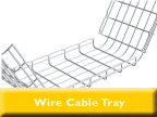
5. Wire Mesh Cable Tray provides:
1. A job site, field adaptable support system
primarily for low voltage, telecommunication and fiber optic cables. These systems
are typically steel wire mesh, zinc plated.
2. standard widths of 2, 4, 6,
8, 12, 16, 18, 20, and 24 inches
3. standard depths of 1, 2, and 4 inches
4. standard length of about 10 feet (118")
Wire Mesh tray is generally
used for telecommunication and fiber optic applications and are installed on short
support spans, 4 to 8 feet.
6. Single Rail Cable Tray provides:
1.
These aluminum systems are the fastest systems to install and provide the maximum
freedom fort cable to enter and exit the system.
2. Single hung or wall mounted
systems in single or multiple tiers.
3. Standard widths are 6, 9, 12, 18,
and 24 inches.
4. Standard depths are 3, 4, and 6 inches.
5. Standard
lengths are 10 and 12 feet.
Single Rail Cable Tray is generally used for
low voltage and power cables installations where maximum cable freedom, side fill,
and speed to install are factors.
What materials / finishes are available for the various cable tray systems?
1. Steel (Min. Yield = 33KSI) (35 KSI for Stainless)
1. Plain: hot rolled
pickled and oiled steel per ASTM A569 (Commercial Quality) or A570 (Structural
Quality)
2. Pre-Galvanized: mill galvanized steel per ASTM A653 CS (Commercial)
or SS (Structural) G90
3. Hot Dip Galvanized After Fabrication: plain steel
which is hot dipped after fabrication per ASTM A123.
4. Stainless Steel: type
304 or 316L fully annealed stainless steel
2. Aluminum (Min.Yield =
23 KSI)
1. 6063-T6 or 5052-H32 alloy per ASTM B209
3. Fiber Reinforced
Plastic (FRP)
1. Polyester and Vinyl Ester resin systems available
2.
meet ASTM E-84 smoke density rating; Polyester 680, Vinyl Ester 1025
3. Class
1 Flame Rating and self-extinguishing requirements of ASTM D-635.
Now that I know what types of cable trays are available, what configurations are available?
1. Straight sections are available to route cables in a horizontal or vertical
plane.
2. Fittings are available to route cables in various directions in
either the horizontal or vertical planes. Typical examples of fittings include
elbows, tees, crosses, and risers. Each of these fittings are available in various
radii and bend angles.
3. Covers are accessories and shouldn't be in here
unless splices etc. are included.
After selecting the type of cable tray and configuration required, what support methods are available?
1. Trapeze Support (Single or Multi-tier)
2. Hanger rod clamps, "J"
hangers
3. Center Hung Support
4. Wall Support
5. Underfloor Support
6. Pipe stanchions or other structures
Each
of these support methods are preferable in different applications. For instance,
trapeze supports may be desired in an application where cables will be pulled
through the cable tray. Center hung supports, on the other hand, are generally
used when cables will be installed from the side of the cable tray. Center hung
supports are especially useful when future cable additions are desired. Wall supports
and underfloor supports are useful when ceiling structure is not available or
undesired. Outdoor installations are controlled by the structures available to
support the cable tray.
Before selecting the type of cable tray, cable tray
configuration(s), and support method desired, what additional information do I
need to supply to the cable tray manufacturer for them to best understand and
satisfy my needs?
1. Where? Job site and installation considerations
1. Outdoor
1. supports
available affect the length and strength requirements
2. environmental loads,
ice, wind, snow, and possibly seismic
3. corrosion requirements affect the
materials and finishes
4. classified hazardous locations affect the cable
types acceptable
2. Indoor
1. support locations available affect the
length and strength of the system
2. industrial installation may require a
200 lb. Concentrated Load
3. commercial or institutional installation may
make system appearance, system weight, and space available important factors
4. environmental air handling area may affect cable types, cable tray material,
or cable tray type and need for covers
5. classified hazardous locations affect
the cable types acceptable
2. What?
1. Type and number of cables to support
1. NEC cable fill requirements
dictate size, width and depth, of system
2. cable support requirement may
control bottom type
3. largest bending radius of cable controls fitting radius
4. total of cable weight determines load to support
2. Future requirements
1. cable entry / exit freedom
2. design partially full or an expandable system
3. support type to allow for needs
Call For Pricing Today at (866) 650-DATA


 Cable Management Racks
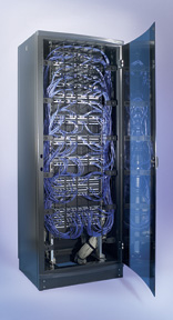





 Snake
Tray
  Snake
Tray


